1. Introduction
Recently, researchers have paid significant attention in the field of two-hop wireless links in both the cases of with and without channel state information. To enhance the reliability of a wireless network, relaying techniques are specially used when the link between the sender and receiver are far away or when the direct link is heavily contaminated with noise and fading. Two of the most widely used techniques are amplify-and-forward (AF) relaying and decode-and-forward (DF) relaying. Sometimes, the gain of a relay is kept constant, irrespective of the condition of the wireless channel (fixed gain AF relay). However, sometimes a relay station taking feedback/acknowledgement from the receiver to adjust the gain is called the variable gain AF relay. The concepts of an AF relay are summarized in [1–3]. For the case of partial channel state information (PCSI) authors in [3] use the AF technique to estimate the outage probability for a cognitive relay network. In [4], the average fading power of a ‘source-to-relay’ and relay-to-destination (R-D) link are derived in a Rayleigh fading environment. The performance of a multi-hop cooperative relay network where the destination receives a signal from both the relay and sender is derived in [5,6] considering two random variables for signal-to-noise ratio (SNR) where one is from the relay and the other from the sender for k-fading. In [7], the AF model is used under the line of sight interference environment. We derived the gain of a relay station in terms of transmitted signal power, the power of interferences, the source-to-relay path gain and noise variance. In [8], the idea of a two-hop wireless link is applied in a multi-way relay channel where multiple users exchange information through a relay terminal. The relaying concept is applied in a cognitive radio network using different cooperative protocols like selection amplify-and-forward (SAF), selection decode-and-forward (SDF) in [9,10] and DF in [11]. Sometimes, among several antennas the best antenna at the transmitting end is selected based on the concept of the water-filling model (to maximize the instantaneous SNR), which is known as transmit antenna selection (TAS). The combination of TAS and MRC under multiple-input multiple-output (MIMO) is analyzed in [12] where the outage probability and bit error rate (BER) of different schemes are compared with the TAS/MRC schemes. The combination of TAS at the transmitter side and SC/MRC at the receiver side is analyzed in [13] with a closed form of solution of the outage probability.
A multiple-antenna system is used in two-hop link to improve the reliability of the link (i.e., reducing the ergodic error probability or the outage probability and to enhance the data rate by transmitting a parallel data stream over the antennas. To reduce the ergodic error probability, the SNR needs to be enhanced. The SNR needs narrow beamforming, an increase in the variation of SNRs, and path diversity. The degree of diversity can be improved in a two-hop wireless link by the applying multiple antennas at the transmitter/receiver/relay stations.
Several approaches can be imposed in context of MIMO in a two-hop wireless link. For example, one approach is to place multiple antennas at the receiver side by making an appropriate separation between the adjacent antennas depending on the channel state characteristics to get an uncorrelated channel response, which is called, receive diversity. In accordance with the multiple receivers, there are different combining schemes, such as selection combining, equal gain combining, maximum ratio combining (MRC), etc. All of which are used to represent the optimum receiver. The second approach is to place multiple antennas at the transmitter side but a signal that is transmitted simultaneously over several antennas will not get the desired diversity gain. In this case, special coding is required at the transmitter. These special codes are called space-time codes. There are widely used codes like Alamuiti, space-time block codes (OSTBCs) and space-time trellis codes (STTCs) are used to get uncorrelated symbols [14]. The STBC of [15] is also applicable in a single hop wireless link to reduce the BER and to increase the throughput.
Sometimes, the best transmitting antenna (TAS) is selected in consideration of the water-filling model. TAS is also used in this paper. Another approach is to use multiple antennas only on the relay station and single antenna on both ends. The reverse model (i.e., multiple antennas) on both ends and a single antenna on the relay are also possible.
In this paper, we investigate several models to observe the relative performance of the two-hop wireless link in a Rayleigh and Nakagami-m fading environment. We used the 8-PSK modulation techniques at the transmitter. The paper is organized as follows: Section 2 presents the detailed mathematical analysis of a two-hop wireless link. Section 3 focuses on the results obtained from the analysis of the previous sections, while Section 4 concludes the findings of the paper.
2. System Model
2.1 Generalized Two-Hop Links
In a two-hop wireless link the received signal vector at the relay can be written as:
where E is the transmitted power, HSR is the channel matrix from the source to relay, x is the source signal, and nSR is the noise vector of source to relay link. Similarly, the received signal vector at the destination is:
where,
y R D / E ( n S R n S R † ) = I N R N 0 E ( n R D n R D † ) = I N D N 0
If the SNR of the links are: ΓSR = ES||HSR||2 / N0 and ΓRD = ĒR ||HRD||2 / N0, then the overall SNR will be [16,17]:
Let the probability density function (pdf) and cumulative probability density function (cdf) of Γi (i=SR and RD) be fΓi(γ) and (γ)FΓi, respectively. Then, the cdf of the combined link is [18]:
where, ω = ΓRD −γ. In case there is a transmit antenna selection among Ns antennas, the cdf will be: FΓSR(γ) = {FΓ1 (γ)}NS.
A similar analysis is also done in [19]. Thus,
(5)
The ergodic capacity of the link is [5]:
where λRD is the output SNR of the destination device. For example: γD = γMRC if an MRC scheme is being used. The symbol error rate (SER) of the destination [16,18] is given by:
The average error probability can be written in terms of the cdf of γD as [16]:
where, a and b depend on the specific modulation scheme.
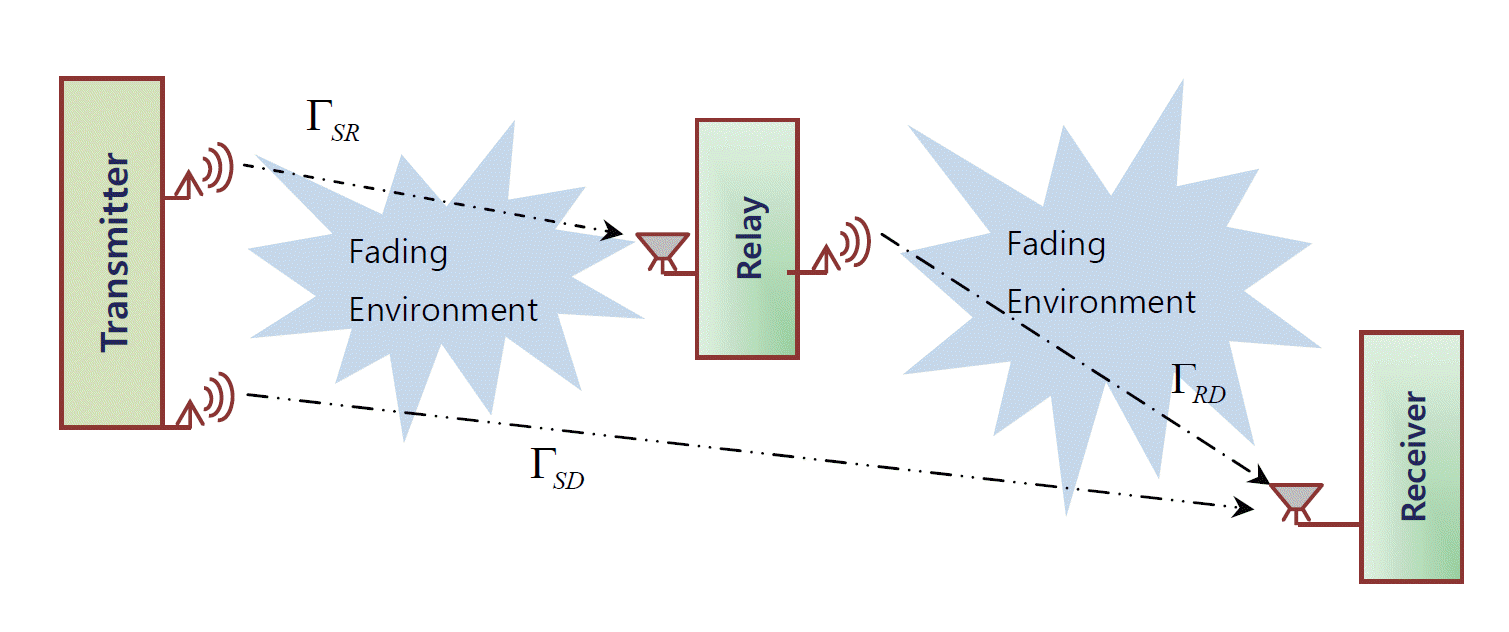
To enhance the reliability of the system, we can use the model in Fig. 1, where the signal is received from both the direct and relayed links.
Let us define two different random variables (RVs) where the one for the relayed link is Δ = ΓSRΓRD/(ΓSR + ΓRD +1), and the other for the direct link is R. The combined cdf is [6]:
where, γD and γm are the average SNR of the direct link and the multi-hop link, respectively. The combined pdf is:
The SER, from Eq. (8), becomes:
The ergodic capacity, from Eq. (6), becomes:
Using the above equations we can determine the capacity and the SER of a two-hop wireless link using a different combination of the number of antennas for a transmitter, receiver, and relay, along with incorporating the weak signal of a direct link.
Another approach in determining the approximate channel capacity of a MIMO link as shown in [20] is,
where, γmin is the minimum normalized SNR for being able to reliably convey the message and S0 is the wideband slope discussed in [20,21]. These parameters can be evaluated as:
and:
Again:
and:
where, x is an RV and indicates the channel gain hi,j of the MIMO link. Nt and Nr are the number of transmitting and receiving antennas. The n-th moment of the RV, E(xn), depends on the pdf of the fading environments. In this paper, the above concept is applied for a two-hop wireless link.
2.2 A Two-Hop Link Aided by a Weak Direct Link
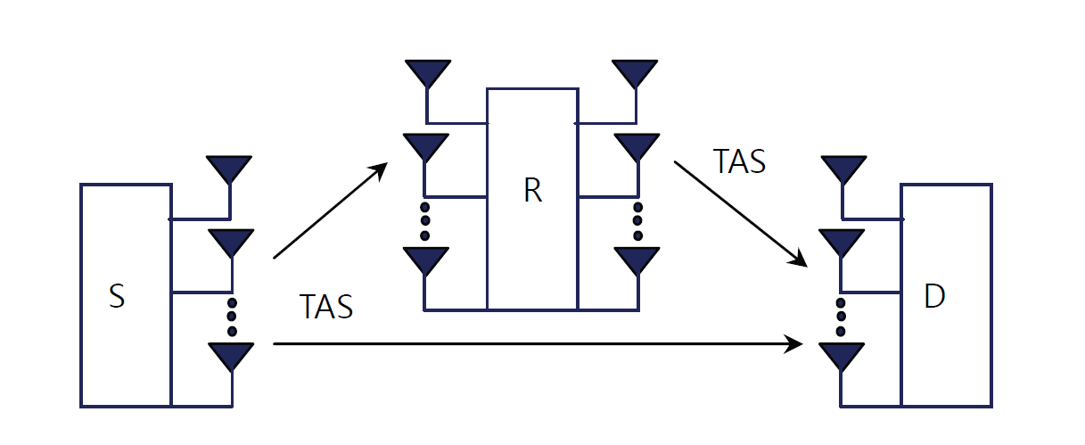
This subsection deals with AF relay using the concept of TAS in [22]. The system model is shown in Fig. 2 where in the first time slot (TS) the sender sends the symbol Sk. Hence, the relay, R, and destination, D, both receive the symbol. In seconds, the TS relay sends the stored symbol, Sk, using TAS. Therefore, the receiver gets the same symbol in the two consecutive TSs.
If the i-th sending antenna and j-th relayed antenna are used, then the equivalent SNR at the receiving end will be:
where, γxy(i) = γ̄xy(i)|hxy(i)|2.
The above approach is applied for a single antenna case in [23] based on OFDM. In the first TS, the received signal at the destination and relay are yS-D=HSD Sk+vn-SD and yS-R=HSR Sk+vn-SR.
In the second TS, the relayed signal is received at the destination as:
where, Hxy is the transfer function between the nodes x and y, and μ is the amplification factor of the relay. We can express the received signal of two consecutive TSs in vector form as:
The above equation resembles a 1×2 virtual MIMO. Hence, SNR will be the sum of two virtual channels like:
where:
The quantity ND is the power spectral density (psd) of the noise of the direct link between the source and the destination, and the quantity NR is the psd of the noise of the source to the relay link. Both of the models above can be considered as a half rate space-time block code since one symbol is transmitted per every two TSs.
2.3 The Alternate Alamouti Scheme in Relayed Communication
Next we will consider another model [24] where two relays are used for a dual-hop AF communication system, as shown in Fig. 3. The system operates in two phases:
Phase 1: The sender sends two symbols S1 and S2, i.e., S = [S1 S2] in two consecutive TSs. The relays receive the signal like:
where:
Phase 2: The relays generate an Alamouti code using
[ Y 1 Y 2 ]
where G is the gain of the relay.
The received signal of destination will be:
which implies
r * ( 2 ) = f 2 * y 2 ( 1 ) + f 1 * y 1 ( 2 ) + n D * ( 2 )
which can be written in matrix form as:
For the channel matrix:
Similarly, the orthogonal relation can be shown for noise matrix like:
Therefore, the SNR will be:
In the case of a conventional Alamouti scheme:
Because of the orthogonality of links only an AWGN model is applicable in both of these cases to determine the symbol error rate.
2.4 Single Relay Full Rate Model
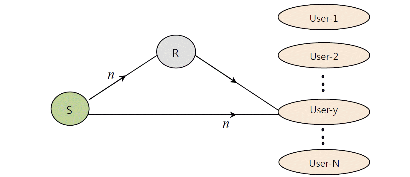
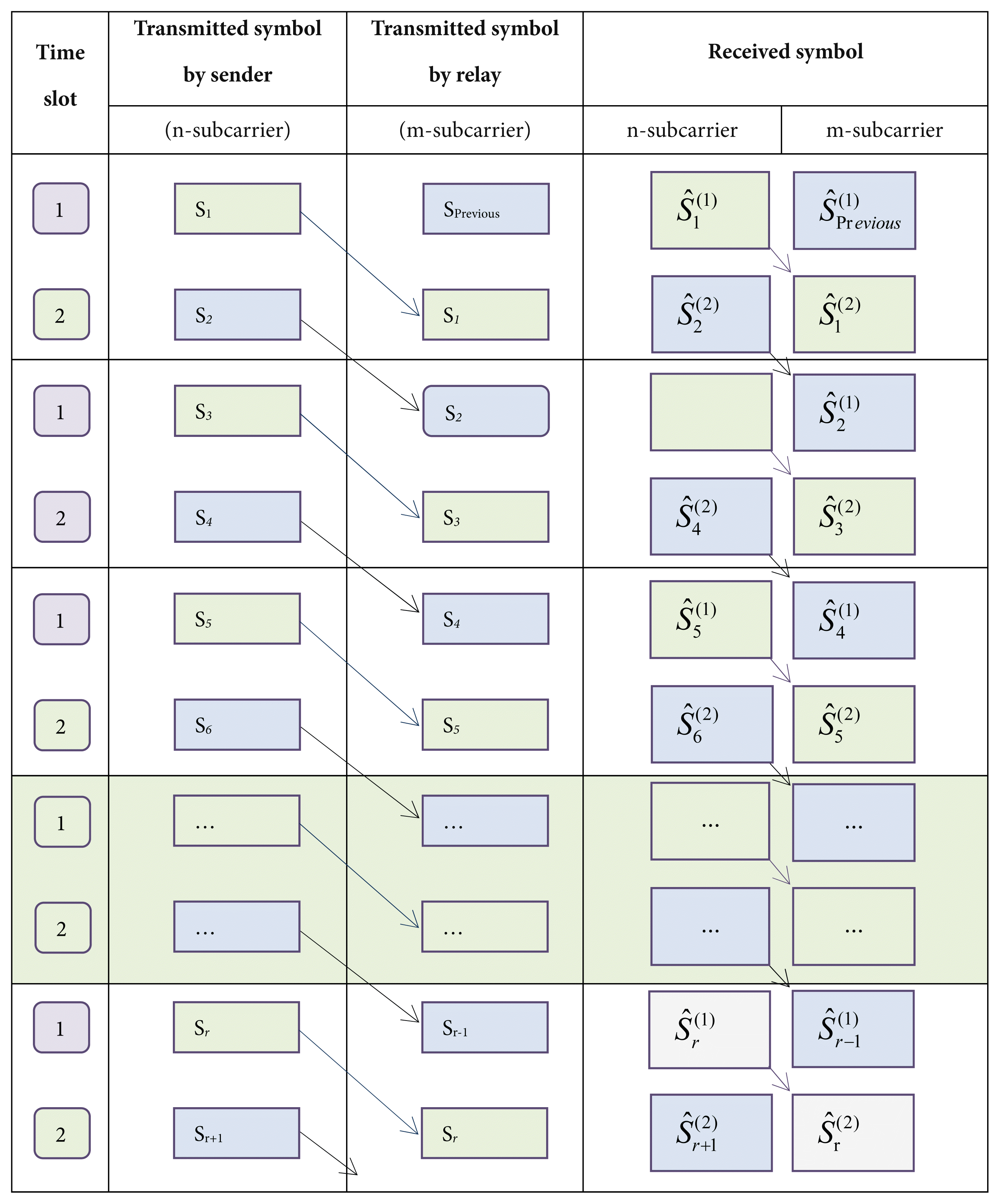
In this paper the two-hop model used in [25] is modified to achieve full-rate space diversity using OFDM. Let the sender send the symbol Sk at the OFDM subcarrier n to user j. Hence, both the relay and user j received the signal in TS-1 like before.
In TS-2 the relay sends the stored symbol, Sk, to user j using another subcarrier, m. Since the user j gets the same symbol Sk in two consecutive TSs it has the option to detect the symbol more precisely. The more complete arrangement of the system is shown in Fig. 4. In the first TS, the received signal applying auto-correlation is:
In the second TS, the received signal will be:
where, OSC(fi) is the i-th orthogonal subcarrier,
S ^ k ( i )
In the previous half rate model, the sender was silent when the relay was in the transmitting mode. Because of the use of an orthogonal subcarrier of the OFDM the sender can now simultaneously transmit with the relay. The transmitted and received signals of the system are visualized in Table 1. An arrow in Table 1 connects the same symbol between two consecutive TSs. Now the symbol detection can be done using the maximum likelihood as:
The instantaneous received SNR is γ1 = |hSR|2|hRD|2γavg and γ2 = |hSD|2 γavg. Since <OSC (fm) OSC(fn)> = 0, hence, the AWGN model is applicable to detect the symbol error probability. Now the probability of the symbol error is: Pe = P(γ1 < ɛ )P(γ2 < ɛ); where, ɛ is the threshold SNR at the receiving end.
3. Results and Discussions
Fig. 5(a) and (b) show the variation of the ergodic channel capacity of the R-D line against the SNR of the corresponding link for Nakagami-m and Rayleigh fading cases, respectively. We used three combinations of antennas when applying the concept of [17,26,27]: NS = ND = 1, NR = 2; NS = ND = 2, NR =1; and NS = ND = NR = 2. The first three cases are drawn for the case of TAS and the next three curves are drawn considering all of the antennas. The performance of the channel is almost fixed in both the Nakagami-m and the Rayleigh fading channels for the case of the TAS because of the use of strongest SNR link. However, in the case of an ordinary MRC scheme, the performance of the link is found to be better in a Nakagami-m fading case. This is because m = 2 with a strong direct link between R and D [28].
It is important to note that the channel capacity was found to be very poor for the case of NS = ND = 1, NR = 2, TAS. Since one link is selected for the case of TAS, the two-hop link resembles the case of a single antenna link and will not get the benefit of the Alamouti or the MRC schemes. The channel capacity was found to be the best for the NS = NR = ND = 2 case. The capacity can be further improved if we combine the Alamouti and MRC schemes, which is not shown in Fig. 5. We were more interested in observing it via simulation, as shown in Fig. 6. Applying the ordinary MIMO formula of a matrix trace under the 2 ×2 MIMO link of both hops resulted in a moderate performance for the Rayleigh fading case, while it yielded very good results for the Nakagami-m fading. Incorporating the weak signal of the direct link (a single antenna case was considered here) enhances the capacity for a Nakagami-m fading case, as compared to that of a Rayleigh fading. This is because there are several strong direct links for the case of the Nakagami-m fading environment. The performance of the single antenna case then becomes comparable to that of the multiple antenna case.
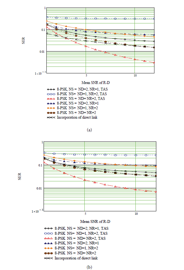
Fig. 7(a) and (b) show the variations of the SER of R-D links against the SNR of the corresponding link for the Nakagami-m and Rayleigh fading cases, using the same combination as shown in Fig. 5. The profile of the SER of TAS case was found to be almost the same for both of the fading cases. However, in the case of all of the antennas being utilized, the SER was found to be better for the Nakagami-m case. A similar explanation is also applicable for the case NS = ND = 1, NR = 2, TAS line as shown in Fig. 5. The SER is found the lowest for the case of NS = NR = ND = 2. It can be further lowered using the Alamouti and MRC schemes, which we verified using a simulation, as shown in Fig. 6. Similarly, incorporating the weak direct signal with the SNR of the 0.2 single antenna link shows that its performance is comparable to the multiple antenna case.
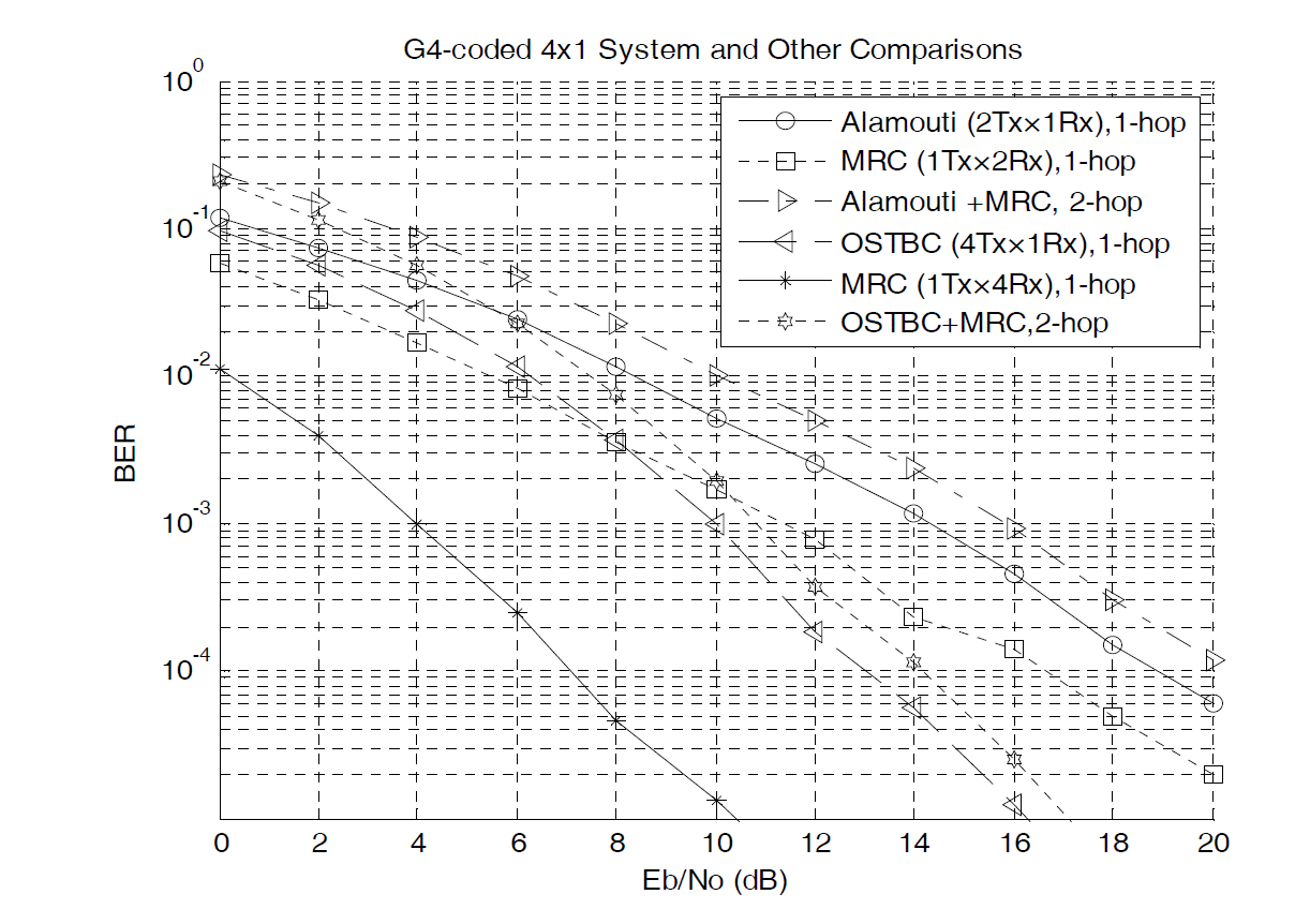
We ran a simulation on MATLAB (using the concept of Monte Carlo) to get the profile of the SER. We used the Alamouti scheme for a single link, the MRC 1Tx×2Rx case, the two-hop link where the first hop is the Alamouti scheme and the second one is MRC, a single hop with OSTBC 4Tx×1Rx, a single hop MRC of 1Tx×4Rx, and a two-hop OSTBC with MRC, as shown in Fig. 6. The curves seem much stepper because of using the BPSK scheme. The combination of the Alamouti and MRC schemes was found to be the best, as shown in Fig. 6. Of course increasing the number of antennas can further enhance the performance, but the cost of the link will be higher.
Simulation work was done separately for determining the normalized channel capacity for four different fading cases. We fully used the MIMO (transmitter, relay and receiver) of four antennas in each stage by using the idea of trace of the channel matrix. Comparisons of our theoretical and simulation results are shown in Fig. 8 for four different fading environments. The statistical parameters of the fading channels are taken as, Gaussian: σ = 0.2, μ = 4; Weibul: λ =1.5, m = 3.75; Nakagami-m: γav = 6, m = 4; and Rayleigh: γav = 6. The analytical and simulation results of Fig. 8 satisfied the concept of Fig. 5 (i.e., the channel capacity under Nakagami-m fading is better than the case of Rayleigh fading). Both of the fading environments showed moderate results in the sense that they were better than the Weibul fading case, but worse than the Gaussian fading case.
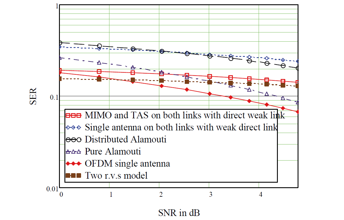
Finally, MIMO and TAS with a weak direct link, a single antenna case with a direct link, the distributed Alamouti scheme, the conventional Alamouti scheme, the full rate OFDMA with two subcarriers scheme, and two r.v.s models were compared in context of SER varying of SNR from 1 to 5 dB (direct link for concerned models). The complete results are shown in Fig. 9. Rayleigh fading was only considered in the case of two r.v.s models and the other modes were almost orthogonal (i.e., immune from severe fading). Among all of the models we used, the OFDM had the best performance. However, this was at the expense of using two sub-carriers for each link.
5. Conclusions
In this paper, we were able to bring most of the recent concepts about two-hop wireless links under small scale fading to find an optimal model. Our findings are as follows: the inclusion of the weak signal of a direct link with the relayed signal resembles a parallel link where SNR becomes an additive like the conductance of a parallel electrical circuit and gives the best performance as compared to any other existing models. Using multiple antennas on both ends and a single antenna on the relay is much better than the case of using a single antenna on both ends and multiple antennas on the relay. Selection of transmit antenna enhances the performance of wireless link compared to the 2×2 MIMO case. This satisfies the concept of the water filling model. The approximate ergodic capacity model, using trace of autocorrelation matrix, gives moderate results, but doing the mathematical modeling for it is much simpler. Finally, the combination of the Alamouti scheme and the MRC scheme gives the best result, but the complexity of practical design is much higher compared to other models. Finally, the concept of MIMO and TAS with a weak direct link case, a single antenna case with a direct link, the distributed Alamouti scheme, the conventional Alamouti scheme, the full rate OFDMA with two subcarriers scheme are included with conventional two-hop wireless communications so that a network planner has a wide range of options to choose the best communication system.


